How to Remove The Pistons Engine Rebuilding parts 2
- Share
- Issue Time
- Dec 17,2015
Fix A Connecting Rod Knock - GM 4.3 V6,May Also Apply To Chevy / GMC350 Cubic Inch V8 Engines.
the exhaust manifolds, the rocker arms and pushrods, and the cylinder heads are removed in REMOVING THE CYLINDER HEADS
To turn the engine over to look at the crankshaft.pushed and pulled on each connecting rod, but not locate any looseness where any rod attached to the crankshaft.But that doesn't mean anything.
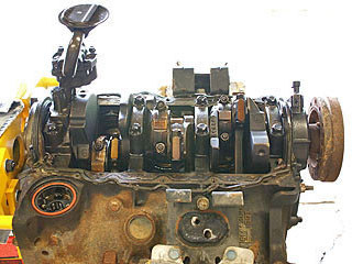
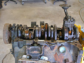
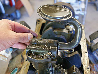
The oil pump and pickup tube are on the right.
TIP:
It's a good idea to mark the cylinder number on the rod cap for each piston.
Caution:
The pistons are supposed to be replaced in the same cylinder they were removed from, so keep track of the pistons.
The connecting rods and caps on this GM engine all have serial numbers etched in them, on the side near the joint between cap and rod.If you don't stamp a number (or series of dimples) in the rod cap, at least write down the serial number for each rod/cap combination.
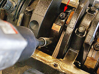
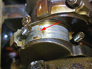
turned the crankshaft so number 1 piston was at top dead center.Then used an impact wrench with a 9/16 inch socket to remove the connecting rod cap nuts (red arrow).
When the nuts are removed from a connecting rod cap, the cap doesn't just fall off. The extremely tight fit of the cap, rod and bearing shells make the cap and rod hold onto the crankshaft journal very tight. Carefully tapping on the cap with a hammer, in a sideways direction, may help the cap separate from the rod and crank journal, but there isn't much room for the cap to move sideways.it's the easiest to simply tap the rod downward as seen in the next photo.
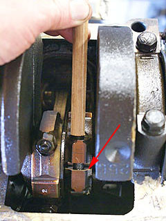
placed a small diameter wooden dowel over the connecting rod studs and tapped carefully with a small hammer.This pushed the piston and rod downward enough to separate the rod (red arrow) from the cap.
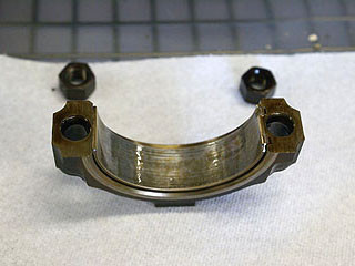
removed the connecting rod cap.Note how the bearing "shell" was still attached to the cap. This is normal.
placed short pieces of vacuum hose over the rod studs so they wouldn't scratch the crankshaft or the cylinder wall when the piston was driven out.
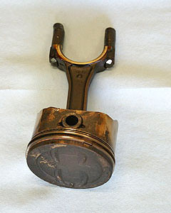
Then pushed on the connecting rod by hand until the piston came out the top of the engine block. On some cylinders the piston would come out by hand, on other had to tap very gently with the dowel to move the piston rings past the slight lip at the top of the cylinder wall.
There is a chance that a piston can fall out before you can catch it, and hit the floor. Placed a plastic bucket under the engine below the cylinder being worked on. This helped, because one time a piston fell before you could grab it and hit the bucket.
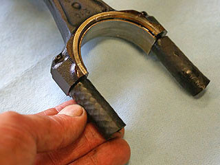
Warnings About The "Ridge" At The Top Of The Cylinder:
the ridge of metal that is commonly found at the top of the cylinders. An older engine often has some wear on the section of the cylinders that are "wiped" by the piston rings, but there is a narrow band at the top of the cylinder that never wears because the piston rings don't touch it. When the piston is away from the top, you can run your fingernail along the cylinder and feel a significant lip or ridge of metal near the top.
Sometimes this ridge of metal must be removed before the pistons are removed, or else the pistons can be damaged as the rings snag on the metal adjacent to the ring groove.
The ridge on this engine was minimal. estimate the ridge was 3 to 5 thousands of an inch. barely feel the slight rise in the metal. With a fingernail to detect it more, and it felt more like a ramp than a distinct edge.
If the cylinders have a distinct lip, then a ridge removal tool must be used to prevent piston damage. Apparently this is some type of hand tool that shaves away some metal as you run it around the top of the cylinder.
The rubber hoses is placed over the rod studs.You can buy rubber "boots" to cover the connecting rod studs. Later, you should buy a pair before you assembled the pistons in the engine.
A "Spun" Bearing:
removed the rod cap on cylinder number 3 while it was positioned near bottom dead center (instead of top dead center), just to illustrate this point.
When you removed this cap, the bearing shell did not come out with the cap. Note the joint between the bearing halves (red arrow). This is not supposed to be this way.
This is a "spun bearing". The small "tang" of metal on the end of the bearing shell has been sheared off or worn away until the bearing had nothing to prevent it from turning with the crankshaft.
The underside of rod cap number 3. Note the dark lines...
presume these are caused by the bearing rotating, or perhaps by heating of the metal caused by the turning bearing.There is no film of oil between the bearing and the cap, so when the bearing moves it will cause some serious wear to something...
most likely the back side of the bearing (accelerating the knock problem), or possibly the rod and cap. Either way, the connecting rod cap has possibley been stretched, so the rod and cap will need to be checked with a micrometer and machined to correct any slight oval shape.

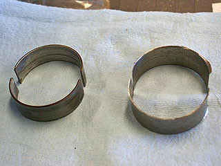
Bearing shells, cylinder 3 and 6.Number 6 is much worse.
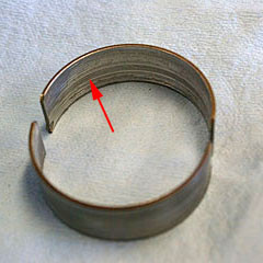
Cylinder 3 rod bearings, closer view.Note the dark line, which may be caused by overheating or lack of lubrication.
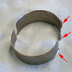
Cylinder 6 rod bearings, closer view.Note the "flange" of metal near the ends (arrows). I suppose this overhanging metal could've been caused by the loose-fitting connecting rod "hammering" on the bearings.
One of these shells was overlapping the other when removed the connecting rod cap. As soon as started using the impact wrench to remove the cap nuts, before the first nut had even turned, It should be tight.
This is one messed-up bearing. THIS was my "smoking gun", the source of the rod knock.
Crankshaft Journal Damage:
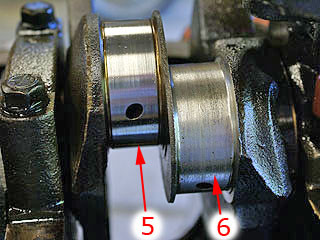
The crankshaft journal for number 6 cylinder was quite rough compared to journal number 5.When ran my fingernail across journal number 5, the surface was quite smooth and only a few slight snags could be felt. Journal number 6 felt very rough... and could feel snags across the entire width of the journal.
Removing The Oil Pump:The oil pump is mounted to the rear-most main bearing cap, and must be removed before the crankshaft can be removed.
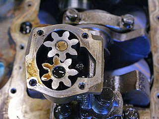
removed the 4 bolts that held the oil pump together.This step isn't necessary (at least right now). I just opened up the oil pump to satisfy my curiosity and see what was inside. Just a pair of gears.
This is a gear-type oil pump. Note that the oil pump needs to be primed before the engine can be run again. filled the pump cavity with petroleum jelly (Vaseline) before re-assembling the engine.
removed the large bolt with a 16mm wrench and lifted out the oil pump.re-assembled the two halves of the oil pump and set it aside.
