how to Remove The Crankshaft Engine Rebuild Part 3
- Share
- Issue Time
- Dec 30,2015
Removing The Harmonic Balancer
To reach the timing gears, the harmonic balancer must be removed. The harmonic balancer fits very tightly on the front end of the crankshaft, and is secured by the snout bolt, which also holds the serpentine belt pulley which drives all the accessories in the engine compartment.BUT... you cannot use an ordinary gear puller to remove a harmonic balancer, because there is section of rubber between the outer ring and the inner metal section.
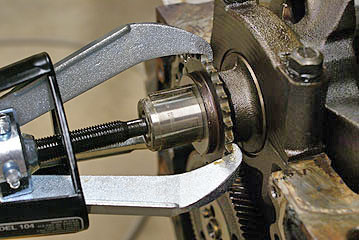
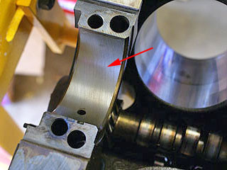
installed the puller plate (red arrow) on the harmonic balancer and turned the hex on the end of the jackshaft to push the shaft into the end of the crank.
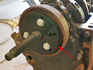
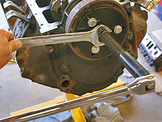
held the jackshaft with a 1-1/16 inch wrench while I turned the back end of the shaft with a 5/8 inch socket and breaker bar.
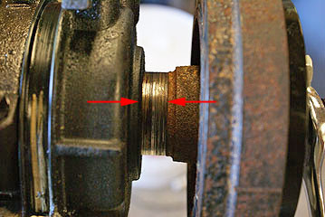
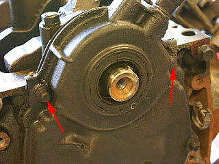
While turning the puller, you could see this gap opening up between the harmonic balancer and the timing chain cover.The shiny area between the arrows is not the crankshaft... it's a smooth part of the harmonic balancer. The front oil seal rides against this surface.Note that the front oil seal is built into the plastic cover for the timing chain, so if the front seal leaks, the cover must be replaced.
Timing Chain Cover:
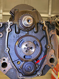
At this point I was able to remove the timing chain cover.The arrows indicate two of the six bolts that hold the cover to the front of the engine block. These bolts require a 10mm socket or wrench.
The big sprocket is for the camshaft.Removing the timing chain simply requires that the cam sprocket be removed. But first there is a "reluctor" for the crankshaft position indicator that needs to be removed.
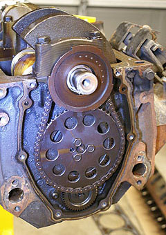
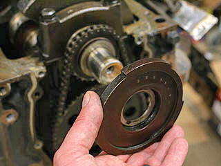
use a 3-jaw gear puller to remove the crankshaft position sensor reluctor.This part has a light press fit.then turn the gear puller (by hand) when the reluctor came off. It might be possible to remove this part by lightly and evenly tapping on the back side with a small hammer.
Note the triangle-shaped marks on the crank sprocket and the cam sprocket, which are aligned for this photo.These marks need to be aligned during reassembly or else the camshaft timing will be off, and that can create a whole slew of problems.
Removing The Timing Chain:
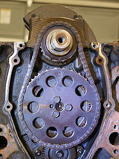
unbolted the camshaft sprocket using an impact wrench and a 1/2 inch socket, and lifted off the chain.The red arrow points to the gear for the balance shaft, which lies directly above the camshaft (when the engine is upright). I believe GM's V8 engines don't use a balance shaft.
use a 3-jaw gear puller to remove the crankshaft timing sprocket. But there was a small problem... the center of the puller has a pointed tip which almost fit inside the 7/16-20 threaded hole in the end of the crankshaft.To prevent damage to these threads,placed a 5/16 inch nut in the end of the crank, and placed the tip of the puller in the center of the nut. and allowed to push against the end of the crank without ruining the internal threads.
Removing The Rear Oil Seal:
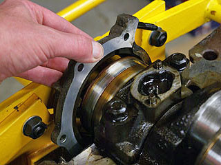
Removed three small bolts and a nut to remove the rear oil seal.The seal assembly slipped off the rear end of the crankshaft easily, but it was trapped by the engine stand, so you couldn't actually remove it until the crankshaft was lifted off the engine.you will need to remember to slip the rear seal assembly over the end of the new crank when I install it.
Removing The Main Bearing Caps:
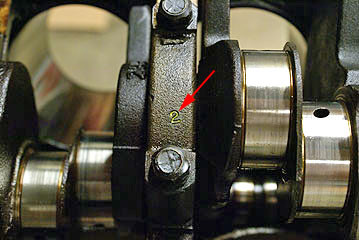
The main bearing caps are numbered 1, 2 and 3.The 4th (rear) cap isn't numbered because it is different from the others.
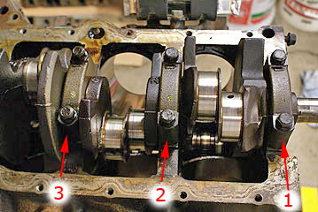
Closer view of the main bearing caps.
(I used a paint marker so the numbers would show up better in pictures.)
Removing Main Bearing Caps:
Removed the main bearing caps using the impact wrench and a 5/8 inch socket.The main bearing caps are quite difficult to lift off the engine block because they fit so tightly in the machined recesses in the bottom of the engine block. so you had to tap the caps sideways with a small hammer to loosen them.
Identifying The Crankshaft:
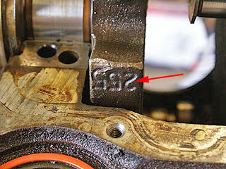
When you was ordering a remanufactured crankshaft, the parts store needed to know the forging number on the crank. The number 255 was molded into the crankshaft in 5 places, so this must be the forging number that the parts store needed.
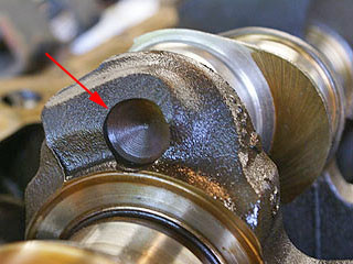
At the rear of the crank, there was this balancing hole (red arrow) drilled into the side of number 6 rod journal, which is consistent with the description of a number 255 crankshaft given by the auto parts store.At the front, there was another balancing hole drilled into the side of rod journal number 1.
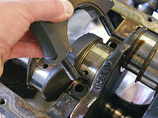
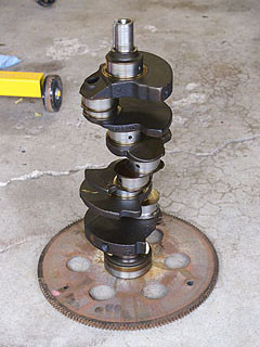
carefully lifted out the old crankshaft and stood it on the front end, and attached the flex plate.tightened the bolts snug. Then I turned the crank over and let it stand on the flex plate. crankshaft should never be laid on the ground, because it can actually warp if it's not supported by the main bearing journals. I think that's more of a problem if the crank gets dropped or bumped.
Removing The Main Bearings:
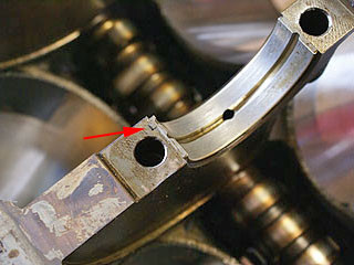
Note the small tab (or tang) on the main bearings. This tab of metal prevents the bearing from turning.
Removing The Main Bearings:
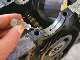
inserted a small flat screwdriver behind the tab and pried gently to separate the main bearings from the engine block.
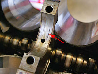
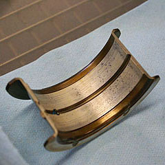
The fourth (rear) main bearing has a different design. The shoulders on the side of the bearing act as thrust bearings, which prevents the crankshaft from moving front-to-back.Note the spots on the bearing. These areas felt slightly rough when you dragged my fingernail across them. This may be normal wear, or it may have been caused by "galling", which is metal-to-metal contact. Galling is a sign of a serious problem, basically failure of the lubrication system to deliver the proper amount of oil. This makes me suspect that there may be a plugged oil gallery near the back of the engine block or in the crankshaft.
Note the diagonal scratch pattern on the engine block behind the 4th main bearing. That's a pattern from the original machining process when the engine was made, so it's a good sign that the scratch pattern is still visible.
Note the small black line underneath the 3rd bearing (red arrow).I'm told that these black marks are caused by the metal getting too hot, possibly from running a little low on oil.