product instruction:BALL JOINT SERVICE SET FOR 2WD&4WD VEHICLES-DN-B1041
- Share
- Issue Time
- Oct 26,2022
ball joint press tool set
WARNING: TO HELP PREVENT PERSONAL INJURY
● Always wear ANSI approved goggles when using this product. Normal use of this product is likely to expose the user to dust and/or microscopic particles containing chemicals known to the State of California to cause cancer, birth defects or other reproductive harm. Always wear appropriate safety equipment and clothing when using this product.
● Study, understand, and follow all instructions provided with this product.
● Before repairing vehicle, block the wheels to prevent the vehicle from moving.
● Check the final alignment of the C-frame press and all tooling with components before exerting pressure to remove or replace a ball joint.
OPERATING INSTRUCTIONS
To Remove a Ball Joint
1. Assemble the Ball Joint Press (1) over the
vehicle’s control arm. Select the correct
size Receiving Tube (3, 4, or 5), and position it under the vehicle’s ball joint.
2. Place the Removal Adapter (7) between the
Receiving Tube and the Jackscrew (2).
3. Then, place the Installation Adapter (6) between the top of the ball joint and the Ball Joint Press. See Figure A.
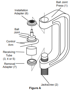
4. Tighten the Jackscrew until the Receiving Tube contacts the vehicle’s control arm.
5. Check the alignment of all the Ball Joint Kit parts, and continue tightening the Jackscrew until the vehicle’s ball joint is removed.
To Install a Ball Joint
1.Clean the vehicle’s control arm, and coat the inside diameter of the control arm with a light lubricant.
2. Insert the replacement ball joint as straight
as possible into the vehicle’s control arm.
3. Assemble the Ball Joint Press over the vehicle’s control arm. Select the correct size Receiving Tube and position it on top of the vehicle’s control arm. See Figure B.
4. Place the Installation Adapter between the Receiving Tube and the
Ball Joint Press. Then, place the Removal Adapter between the ball joint and the Jackscrew.
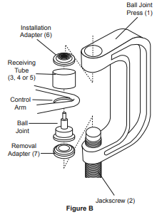
5. Check the alignment of all the Ball Joint Kit parts. Then, tighten the Jackscrew until the vehicle’s ball joint is firmly sealed
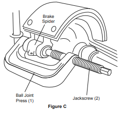
To Remove and Install Brake Anchor Pins
1. To remove the brake anchor pins, remove all
lock ring retainers from the Brake Anchor Pins.
2. Position the Ball Joint Press over the brake spider.
3. Tighten the Jackscrew until the anchor pins
can be removed. See Figure C.
4. To install the brake anchor pins, insert the
brake anchor pins. Then reinstall the lock ring retainers on the brake anchor pin.
5. Unscrew and remove the Ball Joint Press.
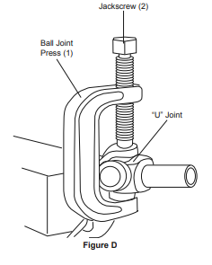
To Disassemble / Assemble a “U” Joint
1. To disassemble a “U” joint, remove any external and/or internal lock rings.
2. Position the Ball Joint Press around the drive shaft yoke and tighten the Jackscrew until the first bearing is removed. See Figure D.
3. Reposition the Ball Joint Press and remove the second bearing.
4. To assemble a “U” joint, clean all dirt and oil from the yoke area.
5. Align the replacement bearing and Ball Joint Press as straight as possible over the yoke. Press the replacement bearing into the yoke,
and reassemble the external/internal lock ring.
6. Reposition the Ball Joint Press and second replacement bearing as straight as possible over the yoke, and press the bearing into the yoke.
7. Reassemble the external/internal lock ring.
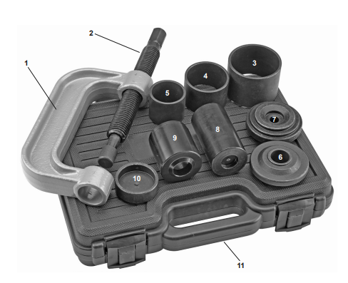
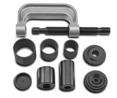
Parts List & Diagram
Part |
Description
|
Qty
|
1 |
Ball Joint Press
|
1
|
2 |
Jackscrew
|
1
|
3 |
Receiving Tube (2-1/4″ L x 2.723″ I.D. x 3″ O.D.)
|
1
|
4 |
Receiving Tube (1-3/4″ L x 2-1/4″ I.D. x 2-1/2″ O.D.)
|
1
|
5 | Receiving Tube (1-3/4″ L x 1-3/4″ I.D. x 2″ O.D.) | 1 |
6 | Installation Adapter (1.122″ L x 0.941″ I.D. x 3″ O.D.) | 1 |
7 | Installation Adapter (1.122″ L x 0.941″ I.D. x 3″ O.D.) | 1 |
8 | Installation Adapter (1.122″ L x 0.941″ I.D. x 3″ O.D.) | 1 |
9 | Receiving Cup
(2-1/2″ L x 2″ I.D. x 2-1/4″ O.D.) | 1 |
10 | Install Cup Adapter
(0.845″ L x 1.879″ I.D. x 2-1/4″ O.D.) | 1 |