Instruction:DIESEL INJECTOR PULLER SET - 14 PIECE
- Share
- Issue Time
- Nov 23,2022
Introduction&contents
Suitable for the fast and safe removal of Bosch, Delphi, Denso, and
Siemens diesel injectors. Set includes keys and deep, open profile
sockets used to dismantle injectors plus adaptors for attaching the slide
hammer securely to the body of the injector. Ball joint allows hammer to
be used in confined areas.
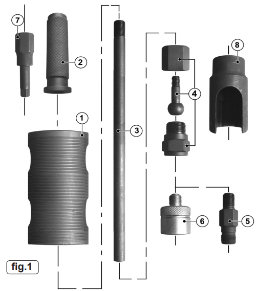
Contents: (refer to fig.1)
Item Description
1. Sliding Hammer
2. Handle
3. Shaft
4. Ball Joint Adaptor (3 piece)
5. Adaptors - (5 Pieces - 4 internal thread, 1 external thread)
6. External Adaptor - (3 piece)
7. Security Hex Key - ½"sq. drive
8. Sockets - (4 pieces - M25, M27, M29, M30 - ½"sq. drive)
Assembly
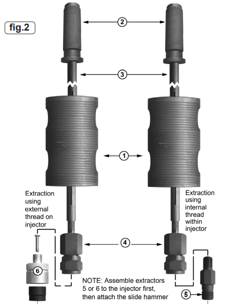
1. Referring to the individual components in fig.1. assemble the Injector Puller as shown in fig.2. overleaf.
2. Use adaptor 6 when the injector is being extracted using the external thread revealed when the injector cap has been
removed.
3. Use one of the adaptors (5) when the injector is being extracted using the internal thread revealed when the inner sleeve has been removed from the injector.
Operation
NOTE:The technique required for removal of the injector will depend on which system is fitted to the vehicle. Always use an external adaptor first if possible. If by using reasonable force the injector cannot be removed, use an internal adaptor.
1. Before working on the fuel system, make sure that the fuel system is not pressurised. Refer to the manufacturer's instruction manual on how to de-pressurise the system.
1.1. Disconnect the injector wires and connections as per the manufacturer's instructions.
1.2. Remove any carbon build up from around the injector.
1.3. Remove the cap from the injector using the appropriate size socket (8). Refer to fig.3.A.
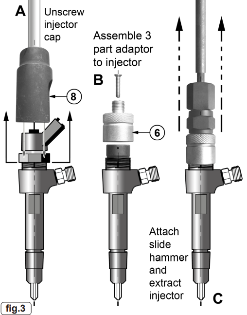
2. Use of external adaptor (fig.3).
2.1. Identify the external thread adaptor (6) and separate the inner black part from the outer silver part by removing the screw from the top of the adaptor.
2.2. Position the black part inside the top of the injector (see B) then place the silver part over it, and screw it down firmly onto the external threads revealed when the cap was removed.
2.3. Install the screw securely thus locking the adaptor parts tightly together with the injector thread and wall in between. This ensures a more secure fastening and reduces damage to the injector threads.
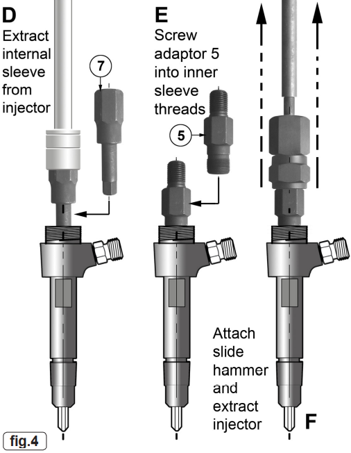
3. Use of internal adaptor (fig.4).
3.1. Remove the internal parts from the injector to gain access to use the security hex key (7). It may be necessary to remove the injectorveins by force. Insert the security hex into the inner sleeve (see D). Turn the security hex anti-clockwise using a 21mm socket to
remove the inner sleeve.
3.2. Screw the appropriate internal adaptor (5) into the threads of the injector and tighten with a suitable spanner (see E).
4. Removing the injector.
4.1. Screw the slide hammer assembly (handle, shaft and sliding hammer) securely onto the adaptor.
4.2. The injector can now be removed using reasonable force on the slide hammer. Be prepared for the sudden release of the injector from the cylinder head.
4.3. If the injector cannot be removed, it may be necessary to consult a main dealer or a diesel specialist, to avoid damage to the engine.
4.4. When an injector has been removed, it is recommended that only a new or refurbished injector is fitted. Follow manufacturers fitting and
safety instructions