- Ningbo Dongning Tools Co.,Ltd
- Professional Chinese Tools manufacturer on automotive speciality tools,bearing puller&heavy truck tools
- Address
- No.6 Falan Rd,Hengjie Town,Ningbo City,Zhejiang,China
- Phone
- +86-574-87216625
- info@nbdntools.com

Jaws need a solid, even edge behind the component. Partial contact on a thin lip, damaged face, or tapered surface can force the jaws outward under load.
Too little reach makes the puller unstable; excessive spread reduces control and can bend legs. Measure the component and access space before selecting the puller.
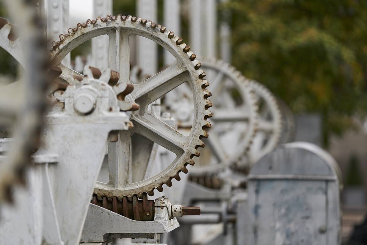
An off-axis screw pulls at an angle and encourages one jaw to lose engagement. Reposition the setup until the screw, shaft, and puller body are aligned.
Where there is no safe outer edge for jaws, use a correctly sized separator behind the bearing ring. Confirm that both separator halves contact the same robust surface.
Snap rings, lock plates, fasteners, and staked features can make a puller appear to slip when the component is still retained. Recheck the service procedure and the part itself.
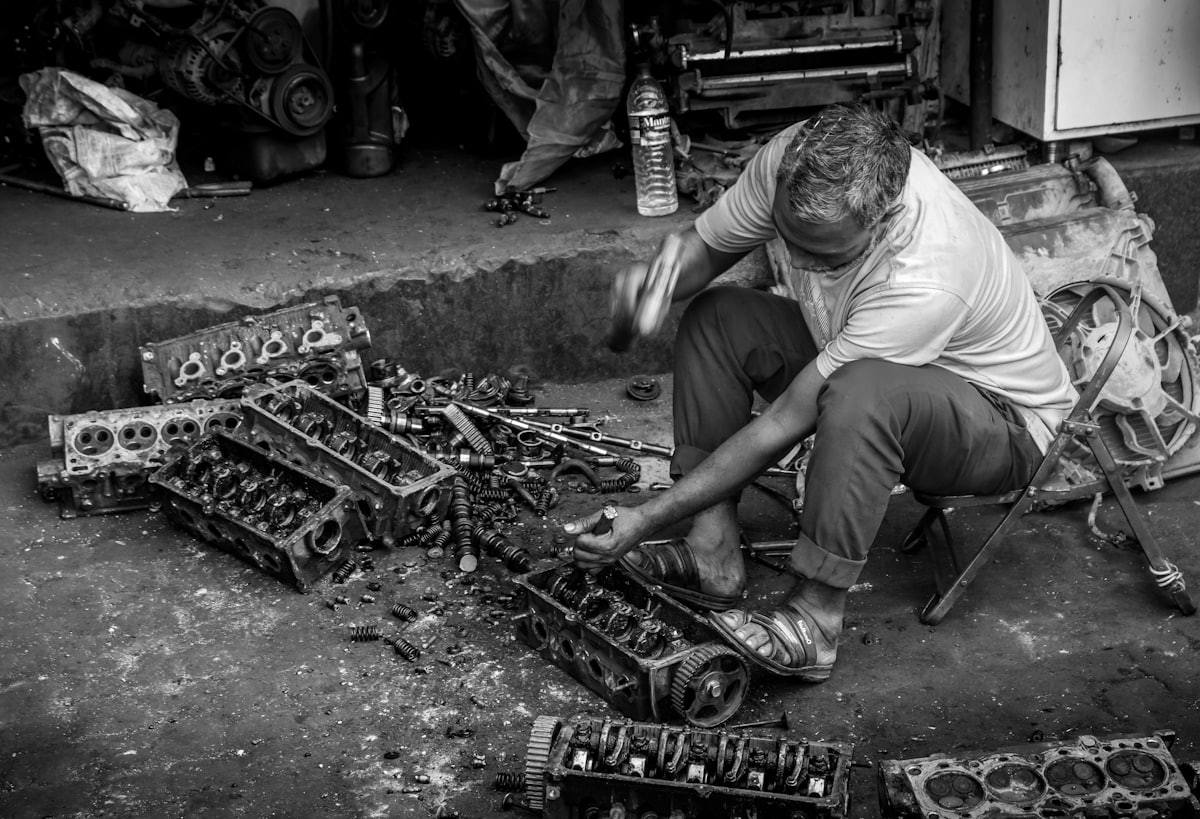
Bent legs, worn tips, damaged threads, and dry forcing screws reduce grip and control. Remove damaged equipment from service and maintain moving parts as specified.
Movement in the housing, shaft, or support stand changes the force path. Secure the assembly and use supports that prevent sudden rotation or dropping when the fit releases.
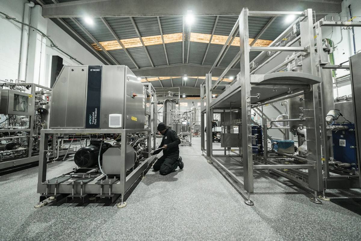
With a hydraulic puller, every adapter and support must be rated for the expected load. Increase pressure gradually and stop at any jaw movement, noise, or component tilt.
Confirm contact, alignment, retainers, condition, and exclusion area before each pull. DNT Tools can help specify puller and separator combinations for common transmission applications.
For a puller, separator, or support fixture matched to your application, contact DNT Tools with the bearing and housing dimensions.